During development of my current project procshape, which is progressing nicely, I found myself often thinking about ways to “weld” together the basic shapes I was creating with algorithms.
I distinctly remember my first tries of creating plant-like 3D shapes and my disappointment with how the intersecting geometry looked under certain circumstances (lighting, Z-fighting, …). Not to talk about the disturbing thought of having vertices and partial or complete triangles that the GPU has to calculate, even though they would never be visible on screen. At that time I tried to brute-force triangles together for a while but discarded the idea, when I realized, that my attempts only made it worse.
Back then, I was barely able to create a simple manifold 3D shape, but with time came more experience and much better understanding on the many aspects involved. So I started to read blog posts, tutorials and research papers about Boolean operations and Constructive Solid Geometry to get an idea on how to implement such techniques into procshape.
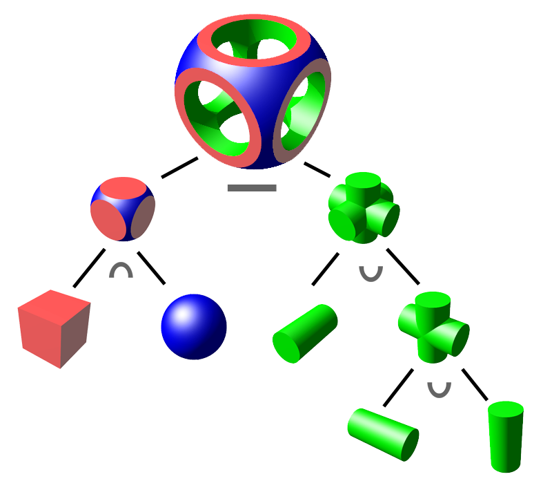
The Image above should give a rough idea of what I’m writing about here. Every relevant Boolean operation is shown and out of three very basic 3D shapes and only four operations, one can achieve complex shapes like the top most shape in the illustration shows.
Boolean Operations
To better understand what is happening in Figure 1, I think it wise to first look at the theory in 2 dimensions, before looking for a way to tackle it in 3 dimensions.
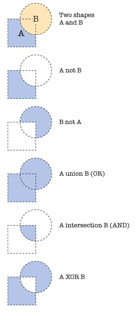
Figure 2 shows all possible Boolean operations, illustrated on the same two polygons which are: NOT, OR, AND and XOR.
NOT can be expressed as every point that is inside polygon A but not inside B, and vice versa, effectively performing a subtraction of one from the other.
OR can be expressed as every point that is inside either polygon A or B, therefor also known as union.
AND can be expressed as every point that is inside of both polygons A and B and thus represents the intersection of A and B.
XOR can be expressed as every point that only lies in either polygon A or B, leaving out all points that lie on the intersection of A and B.
How CSG builds on Boolean operations
When trying to adapt the theory from two dimension into the third, there are several pit falls to consider along the way.
I used the word “relevant” on purpose before, when describing Figure 1. The operations we saw in 2D in Figure 2 are all relevant when dealing in two dimensions, but things change in the third dimension. First of all, the representation of “solids” changes rather significantly, while in 2D you only need to consider polygons that all share a single plane, a solid or polyhedron in 3D is usually represented as a closed, manifold (hopefully) mesh of polygons, lying on arbitrary planes with a consistent winding order (though there are other common representations, in this post I’m only trying to cover closed 3D polygon meshes). The underlying data available is therefore limited to infinitely thin polygons lying on arbitrary 3D planes that form the hull of a polyhedron, where its inside is considered as being solid.
To perform Boolean operations on such meshes requires an approach that takes into consideration, there only being surface data and not actual solids. A possible solution is to perform a number of ray tests using the information provided by two 3D meshes to find where they intersect each other and use this information to divide the surfaces into a number of sub surfaces, distinguished by the fact of being either in- or outside of where the two meshes intersect. These sub surfaces can then be used to perform the Boolean operations using the fact, that we now know whether it is in- or outside.
There are, to my understanding, three different 3D Boolean operations:
Union
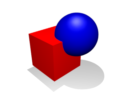
To get a new, manifold and closed mesh, representing the union (Fig. 3) of mesh A and B, one simply discards all sub surfaces that are marked as being inside of the intersection. The remaining sub surfaces form a mesh with the desired properties, given that the input meshes meet that same requirement.
Difference
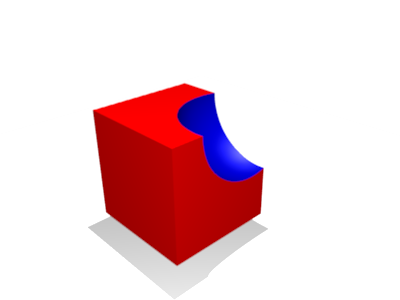
The difference (Fig. 4) of mesh A and B is the combination of all surfaces marked as outside from mesh A, combined with all surfaces marked as inside from mesh B with inverted face winding for the inside surfaces.
This is the only operation, where changing the order of the input meshes leads to different results.
Intersection
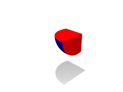
The intersection (Fig. 5) of mesh A and B is the combination of all surfaces that are marked as inside without touching their face winding.
All three (four, if you consider the order of a difference resulting in different outputs) described Boolean operations produce closed and manifold meshes, that in turn can be used as input in further Boolean operations. There are only three instead of four basic Boolean operations in the third dimension, because only the equivalent of NOT, AND and XOR from the 2D operations described earlier, actually produce closed and manifold polyhedra when using the sub surface solution. If you consider what the equivalent of OR in 3D would perform, means that the resulting mesh could no longer meet the requirement of being manifold, since there are now faces inside the closed mesh.
This also holds true, if one wants to perform a Boolean operation that “hollows” out one mesh with the shape of another mesh. In this special case where there are no intersections of faces between the two meshes. The resulting mesh would look unchanged from the outside, but if one were to either place a camera inside, or perform another operation to create an opening on it, the subtracted shape would be evident and displayed correctly.
More, when it actually works...
This only scratches the surface of what needs to be done to implement the algorithms required to perform such operations, but I think I’m on the right track here, to get me some sweet Boolean action in procshape soon.
While working out the details, I doodled many triangles to work out what special cases I might encounter, when suddenly, one of them seemed to be oddly looking back at me…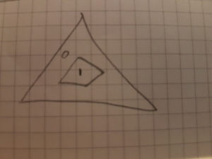
What began as the special case, where a single triangle (marked “O”) is intersected by several others, forming a closed loop entirely inside said triangle (marked “I”), lead me to play around for a bit in Inkscape, which in turn resulted in this:
I recommend the following reading material, that helped me a lot, to dive in deeper and get a better understanding:
My next post will likely feature some visuals of my implementation, once it’s finished and/or working.

Nice one bro! Thank you for sharing what you are learning. Fascinating stuff!