In the last post I wrote about how I created elevation, biome colors and put it all together on a 2D map. In this post I’ll go one step further and instead of mapping my noise functions in 2D space, I map them directly in 3D space.
I started out with the following assumptions:
- A noise mapped on a unit sphere would be tiling seamlessly
- The larger the radius of the unit sphere, the more peak noise values could be mapped (larger sphere = more points close to 1 and -1)
- A texture can be mapped with Mercator Projection
- 2D height maps can be extracted with the least amount of distortion around the equator, so in theory I can apply a base rotation to my unit sphere to offset the equator where I need it to be
If those assumptions hold true, I can theoretically render a planet in 3D as viewed from space and select a point on it, to extract a 2D height map for rendering “levels”.
The Noise
In the previous post I generated 3 unique noises, 2 to get a height map and one to get respective humidity. In the 3D version nothing changes about the amount of unique noises but the implementation differs in one aspect. In the 2D version I had to make the noise “tile-able”, for that you need a noise function that allows for at least 4 dimensions (see this for more information). In the 3D version the noise is already “tile-able” with a 3 dimensional noise function, since I’m using a unit sphere to map the noise (I’m not sure if experts would agree with my assumption, but for my purposes this works more than good enough). This leaves me with one more dimension that I could use to get multiple noises per physical point on the sphere, although with the restriction of the same resolution for each noise. More on that later…
My first attempt to implement a spherical noise was rather slow and one of the main culprits was calculation of the 3D point coordinates for the noise function. Since I want to be able to adjust the “equator” of my sphere to later extract 2D height maps, I also ran into the gimbal lock problem of Euler angles. This lead me to quaternions and quaternion spatial rotation, where I found (with some much appreciated help of a mathematician friend of mine) a solution for my problem at hand and also for potential future problems with animation.
After implementing the rotation(s) with the help of quaternions, I got a significant speed boost while calculating coordinates. So I went on to implement all of it to render my first planet.
Vertex Color vs Texture
Until now, I tried to stay away from using textures on my models, because I got sufficiently good looking models without having to slap on a texture in the first place. With planets that changed. Real time rendering allows only for a limited number of vertices/polygons and creating a mesh with more than a couple ten thousand vertices gets slow really fast. So picking a reasonable number of vertices for my planet model left me with rather ugly looking planets:
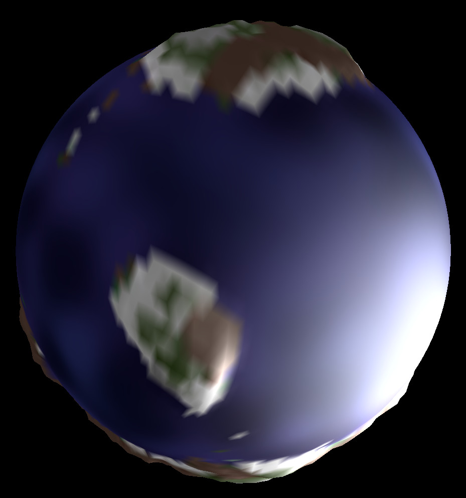
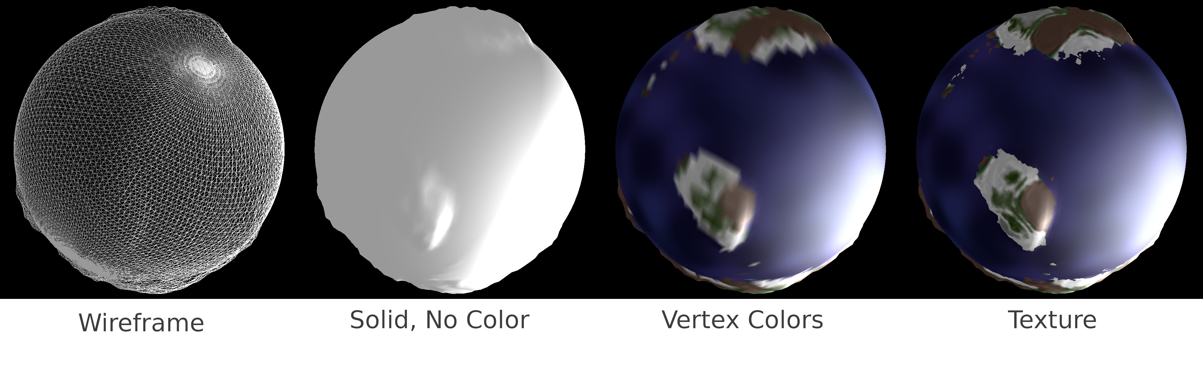
So I went on to create a texture file (using Mercator projection) with higher resolution to slap onto my planet model. This brought its own set of problems with it, swirly poles and jagged seams. Some more research on the interwebs and I found out that this is a rather common problem. This helped a lot, even though I’m not using the unit icosahedron method as is described and implemented there, I still got a better understanding of the problem and how to fix it. The end result is again enough for my needs:
Object Placement
In my TODOs there was the object placement (plants, rocks, and so on…). I opted for an easy solution, implemented again with noise functions. My criteria is, that the biome influences the concentration of one object type, but also using temperature (altitude) to get the same object in several different biomes with different density. So, as mentioned earlier, I use one 4D simplex noise function where 3 dimensions serve again to map the unit sphere and the remaining dimension will serve me to evaluate which, if any, object will be placed. Because I don’t want to go through all possible points in a level, I use the same resolution for object placement as for the height map and apply a positional offset that I get from my remaining dimension. My 4th dimension will thus contain:
- x/y offset (2 values)
- object type (1 value, combined with biome)
- object density (1 value, to decide if the object will be placed at all)
This will assure more or less clean placement since I know the coordinates and inclination of the ground at every possible placement point and it guarantees me only one object will be placed per quadrant on the map. Further down the road I could add object properties to enable the placement of a “rock” beneath a “tree”.
To test my theory I created a little placement test as shown below:

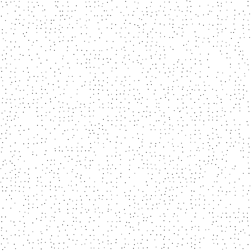
But since I really only know if it looks any good when I see it, this remains on the TODO list until I can test it thoroughly.
Next I’ll be extracting a 2D height map as described before

Pingback: Creating Planets Part III – tizis devlog
Pingback: Creating Planets IV – tizis devlog